Tennis Court Floodlights: Why Are the Baselines Still Dark After an LED Retrofit?
- VKS
- Oct 29, 2026
- Blog
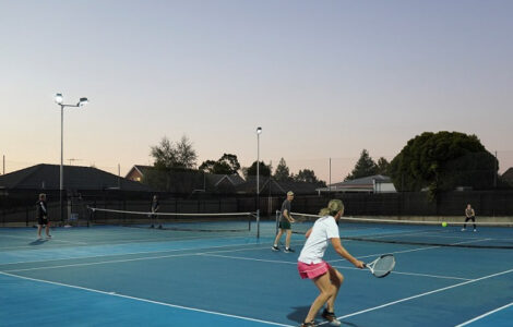
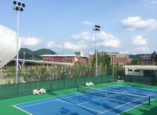
A complaint about the baselines can be awkward for a contractor who has just finished replacing the tennis court floodlights. The invoice might suggest a successful upgrade. The players' view from the back of the court could tell another story. With an LED replacement, putting the bracket back on the old pole does not put the light back in the same places. Take the installation schedule and a court plan to the evening inspection. There is a good deal to establish before anyone can sensibly quote for extra wattage.
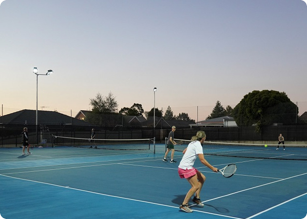
Where Does the Light Fall Short?
Have the player point out where visibility becomes difficult, rather than relying on the description "dark baselines." VKS's tennis court lighting page gives the broader application context. For the visit itself, you need to locate the complaint on this court.
Both ends look dark
Compare the service boxes with the two ends. A strong overlap near the middle would help explain why players have a different impression from the person looking at an average lux figure. The middle counts in that average, after all. On the measurement sheet, retain every point and find the minimum. For a project using Emin/Eavg, divide that minimum by the average to obtain uniformity. Present both figures with the grid so the owner can see what the overall result includes.
One corner is noticeably worse
Start with the equipment serving that corner. Compare it with the opposite side: same optical code, same output setting, same mounting angle? Look for an obstruction or a damaged lens as well. A local fault deserves a local investigation. There is little value in changing every fixture before checking the one area where the pattern differs.
What Changed During the Replacement?
Keeping the old poles saves a part of the installation work. It also leaves the designer working around their existing positions. The approved proposal should show how the replacement optics were intended to work from there.
Read beyond the wattage label
Match each model and optical code to its IES or LDT file. Record pole positions and mounting heights, then check lens orientation and aiming. A broad beam and a narrow beam can have the same electrical rating while putting their useful light in different places. The choice of LED sports lighting therefore needs to account for the throw from each existing pole.
Also check the controls. Was the survey carried out in the normal playing scene, or was part of the system dimmed? A calculation that assumes full output cannot explain a test performed at a reduced setting. Missing records from the old installation limit the comparison you can make. In that case, report how the current installation performs against the agreed criteria and leave the unmeasured earlier performance out of the claim.
How Should You Check the Court After Dark?
Arrange one survey that the contractor can repeat after making adjustments. It will become the reference for deciding whether the correction worked.
Keep the measurement points fixed
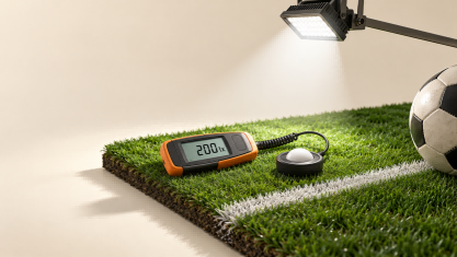
Before the visit, settle the grid spacing, measurement height and survey boundary using the method specified for the project. Include the required run-off areas. With those details on the plan, the person carrying the calibrated meter knows exactly where to take each reading. The fixtures need time to reach stable output. Note the operating scene beside the results so the next visit uses the same conditions.
Show which readings belong to each baseline in the survey, then calculate the required average, minimum and uniformity. Adding color to the grid can make a report much easier to discuss. The owner can point to the area in question while the installer checks which beams serve it. Save the photographs too, as a record of the visit, alongside the meter readings.
Connect the readings to physical checks
Have qualified personnel inspect the brackets, tilt settings, optics and electrical operation. Dirt, damage or a blocked beam may explain part of the pattern. Compare the observed angles with the installation record. Be careful about assigning a low point to the fixture nearest it. Check the direction of that fixture's beam before deciding it has lost output.
Can the Existing Fixtures Cover the Baselines?
The survey gives the designer a problem that can be tested in software. Check that the model contains the surveyed pole coordinates and the photometric data for the installed optic. Otherwise, the proposed adjustment starts from a different installation from the one outside.
Try an aiming change and check its consequences
Compare revised aiming with alternative distributions where the luminaire allows them. Different throws may call for different optics around the same court. Watch what happens beyond the weak baseline, too. Tilting a fitting can put a bright source into a serving player's sightline; widening its beam can send more light past the fence. Check glare, boundary spill and uplight alongside the court readings.
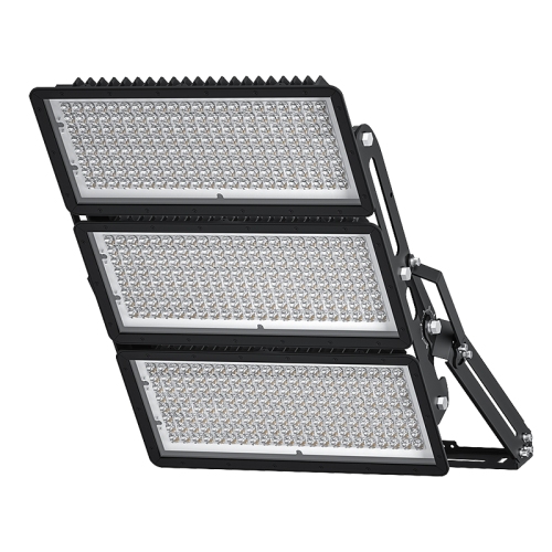
With the G06 Vision 100-320W Asymmetric Floodlight, for instance, the options include symmetric and asymmetric distributions and an adjustable U-bracket. Which option belongs on this court is a calculation to request from the supplier. If the modeled correction remains below the target, fixture output or locations may have to change. An energy-saving claim needs its own explanation, too. Re-aiming at the same load for the same hours leaves electricity consumption unchanged.
How Can VKS Help With the Revision?
Shenzhen VKS Lighting Co., Ltd. provides optical selection and lighting simulation for sports projects. For a baseline complaint, that support can help compare the proposed distribution with the pole arrangement already on site.
Send the survey with the request
Use the project enquiry form to share court dimensions, pole positions and heights, fixture and optical codes, operating settings, and the measured grid. Include the required lighting class or acceptance criteria. This gives VKS the information to assess an optical or aiming revision. The contractor will also need the marked plan again for acceptance readings at the original points. Store the final settings and any agreed deviations with it for whoever maintains the court next.
Conclusion
A return visit is easier to justify when it answers the player's original complaint. Take the readings at the baseline, examine the installation that serves it, and work through the likely corrections in the model. The acceptance visit then has a clear purpose: establishing what changed at the same measured points, with player sightlines checked as well.
FAQs
Is a high average lux reading enough for acceptance?
An average on its own leaves too much out. Ask for the lowest readings and the uniformity result, together with the other criteria in the specification. Check where those low points occur on the court plan.
Can the existing poles stay in place?
That depends on their geometry. Have the designer try suitable optics and aiming from the surveyed positions and heights. The club can then discuss retaining the poles with a calculation in front of it, rather than a promise based on wattage.
What should be recorded after re-aiming?
Keep the final aiming angles, optical codes, operating scene and repeated lux grid. Record remaining deviations and who accepted them so a later investigation has a usable reference.